Electronics Signal
All communication between electronic components are facilitated by electronic signals. There are two main types of electronic signals: analog & digital.
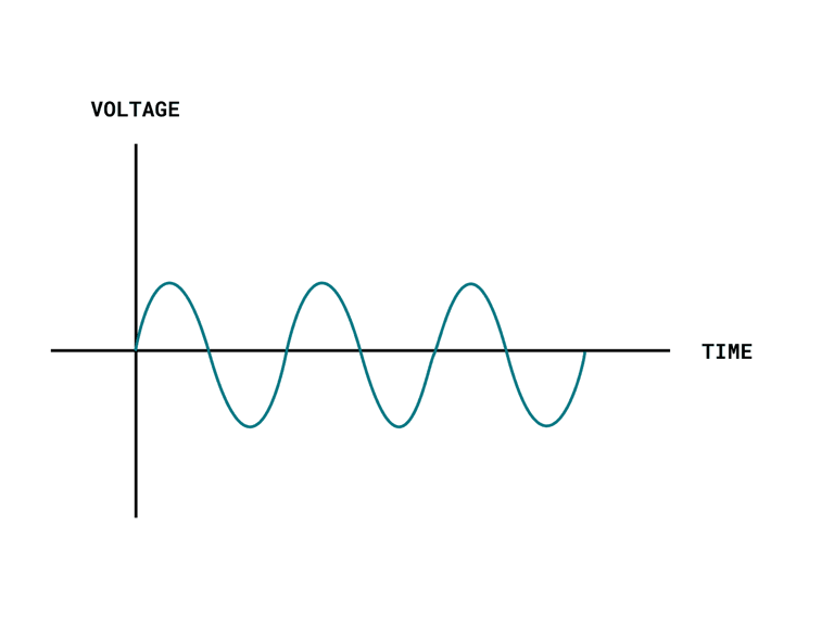
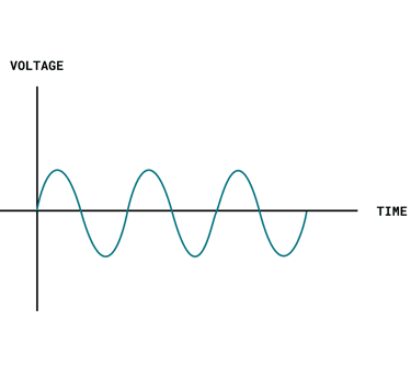
Analog Signal
An analog signal is generally bound to a range. In an Arduino, that range is typically 0-5V, or 0-3.3V.
If we for example use a potentiometer (an analog component used to change the resistance of a circuit), we can manually adjust this range (0-5V). In the program, this is represented in a range of 0-1023, which is a 10-bit resolution.
If we write an analog signal using Pulse-Width Modulation (PWM), we can use a range between 0-255, as we are using an 8-bit resolution.
15
Trusted by Experts
Industry Leaders
Digital Signal
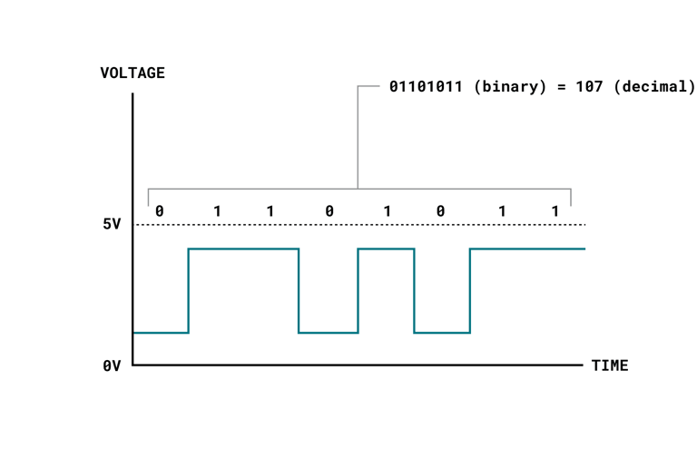
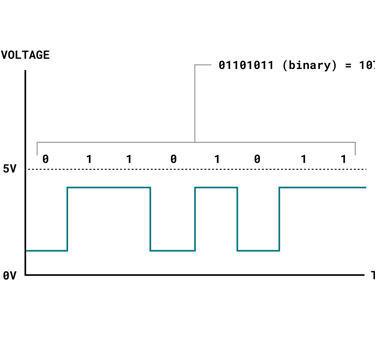
A digital signal works a bit different, representing only two binary states (0 or 1) that are read as high or low states in the program. This is the most common signal type in modern technology.
You can easily read and write digital signals on an Arduino, which is useful to for example read button states, or to turn something on or off.
Digital signals might seem very basic (just 0 or 1), but are actually way more advanced. For example, we can create a sequence by sending a high or low state rapidly a number of times. This is known as a binary sequence or a bitstream.
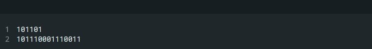
Let's take a look at two binary sequences:
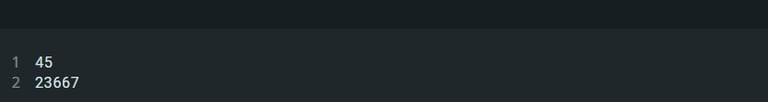
Which in decimal format is:
This is a clever way of sending large amounts of data from one point to the other, by rapidly sending high & low signals. In order to interpret the data from the signals, we use Serial Communication Protocols.